How Should Buyers Specify Three-Way Globe Valve Port Mapping and Fail Position for Batch Process Changeovers?
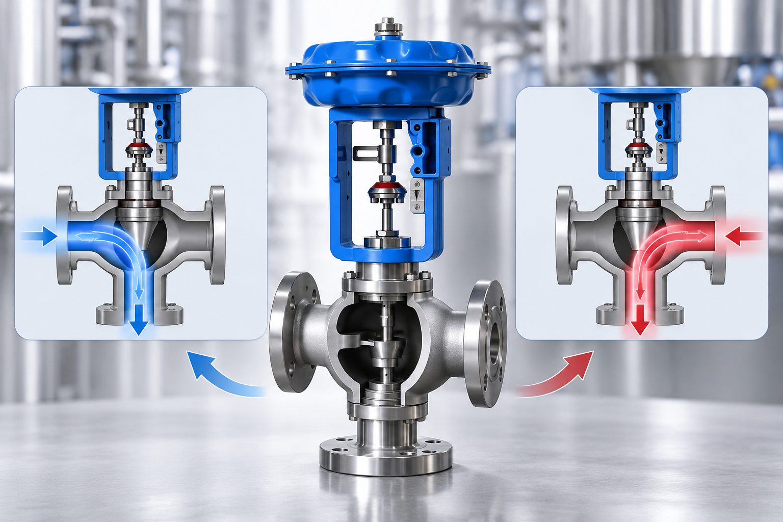
Specifying a three-way globe valve for batch process changeovers requires a clear definition of how fluid should move during production, switching, and shutdown. A valve may provide the required mixing or diverting function but still create problems if its internal flow arrangement does not match the piping diagram or if the actuator’s fail position sends fluid to an unintended destination. This becomes important when several vessels or process stages share common lines. For process engineers and technical buyers, the specification should connect port identification, operating sequence, pressure conditions, actuator action, leakage requirements, and control-system interfaces before the complete assembly is approved.
What Flow Paths Should Be Defined Before the Valve Is Selected?
A batch process may direct fluid between production vessels, circulation lines, bypasses, or cleaning systems. Each operating state should therefore have a clearly defined flow path.
Why Is a Port Schedule Necessary?
A piping and instrumentation diagram shows the main process connections, but it may not fully describe how the valve should behave throughout every changeover.
For example, fluid may enter a production vessel during normal operation and return to a circulation line during preparation or cleaning.
A simple operating schedule can remove ambiguity:
|
Operating state |
Required information |
|
Normal production |
Active inlet and outlet ports |
|
Batch preparation |
Required circulation path |
|
Changeover |
Permitted intermediate flow |
|
Shutdown |
Ports that remain open or closed |
|
Loss of energy |
Required final flow destination |
This schedule gives process engineers, automation engineers, and the valve supplier a common reference before the final configuration is chosen.
Should Intermediate Valve Positions Be Included?
Yes, if the process can experience temporary mixing or simultaneous flow while the valve moves.
For some batch systems, a short period of overlap between two paths may be acceptable. In others, even brief cross-flow between streams can create contamination or process instability.
The required behavior during movement should therefore be defined, not only the two end positions.
How Should Mixing and Diverting Functions Be Evaluated?
A three-way valve may combine two incoming streams into one outlet or divide one incoming stream between two outlets. These functions should not be assumed to use the same internal arrangement.
Why Should Port Identification Be Confirmed?
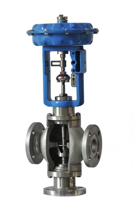
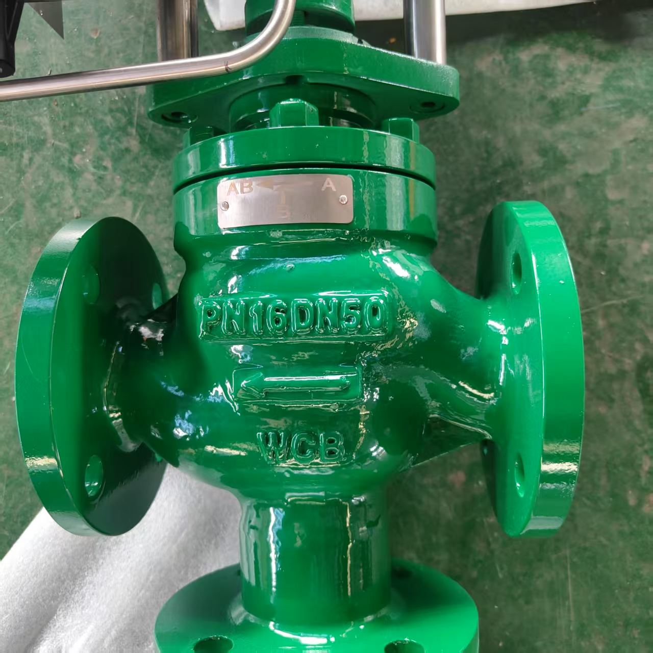
Port letters are not always used identically across different valve designs. Buyers should therefore check the sectional drawing rather than assume that a particular port designation always represents the same inlet or outlet.
The drawing should show flow direction and how the ports connect as the valve moves.
The wider control valve category provides context for control-valve functions, but the actual port relationship must be confirmed for the specific application.
What Problems Can an Incorrect Arrangement Cause?
A wrong flow arrangement may direct fluid toward the wrong vessel, prevent the required circulation path from opening, or create an unsuitable pressure drop.
This is particularly important in chemical processing applications, where different production stages or cleaning sequences may share pipework.
Before technical approval, the process team should confirm whether any simultaneous connection between streams is permitted during valve travel.
How Should the Required Fail Position Be Specified?
Fail position should be based on what the process must do after loss of instrument air, electrical power, or control signal.
For a three-way valve, terms such as fail-open or fail-closed can be incomplete because one path may close while another opens.
Which Flow Path Must Remain Available?
The system may need to maintain circulation, isolate a vessel, redirect fluid to a safe return line, or remain in the last operating position.
The specification should describe the required final port connection instead of only stating actuator movement.
For example, “fail closed” does not tell the supplier which port closes or whether another path remains open. The final state should therefore appear in the approved port schedule.
Why Must Actuator Movement Match the Port Arrangement?
The direction of actuator travel determines how the internal trim changes between flow paths.
For pneumatic operation, the spring-return direction should be checked against the required final position. Electric actuation may require its own loss-of-power strategy.
The actuator category provides a reference for available actuator types, while final selection should follow the required valve force, process sequence, and fail action.
Where the control system uses interlocks, position feedback should confirm that the valve has reached the intended state before the next batch step begins.
What Process Data and Leakage Requirements Should Be Confirmed?
A port schedule defines where fluid should go, but it does not prove that the valve can handle the required flow and pressure conditions.
Why Should Each Flow Path Be Evaluated Separately?
Different paths may have different flow rates and pressure losses. A circulation line, for example, may operate differently from a connection feeding a process vessel.
The supplier should receive minimum, normal, and maximum flow where relevant, together with inlet pressure, outlet pressure, temperature, and fluid properties.
If the valve is expected to regulate flow during changeover rather than only switch direction, expected operating travel should also be reviewed.
How Should Seat Leakage Be Specified?
A closed port may need to prevent fluid from entering another process line. The required leakage performance depends on the consequences of that transfer.
A general statement such as “tight shutoff” is not enough when unintended mixing is unacceptable. The purchase specification should state the required leakage criterion and the pressure conditions under which it applies.
That requirement can then be compared with the proposed seat construction and test procedure.
What Should Be Verified Before the Complete Assembly Is Approved?
The final technical review should confirm that the valve, actuator, accessories, and control-system interfaces operate as one assembly.
Which Functional Checks Should Be Included?
Where required by the project, functional testing should confirm the intended port connections, actuator movement, position feedback, and fail action.
The inspection procedure should identify which valve position corresponds to each process state and how the assembly is expected to respond when energy is removed.
The globe control valve category provides context for related valve constructions, but the final test procedure should be based on the specific assembly.
What Documentation Should Be Retained?
The purchasing file should include the approved valve drawing, port schedule, process data sheet, actuator information, accessory list, leakage requirements, and agreed inspection records.
The same information should be available during commissioning so the installed flow paths can be checked against the control-system logic.
Any change to the trim arrangement, port identification, or actuator action after technical approval should trigger another engineering review.
Professional Technical Support from Miwival
Miwival supplies industrial control valves and automation equipment for chemical processing, pulp and paper, power, and other process industries. Its Three Way Globe Control Valve product information covers mixing and diverting functions, pneumatic and electric actuation, different bonnet configurations, and seat-leakage requirements. For batch applications, engineering teams can provide operating conditions, required flow paths, actuator action, control signals, and inspection criteria for technical review. Miwival’s published quality procedures include material inspection, machining and assembly checks, pressure testing, and final inspection, giving project teams defined points for confirming the valve and actuator assembly against approved requirements before delivery.
Conclusion
A three-way globe valve for batch process changeovers should be specified according to the intended flow paths and operating sequence rather than connection size alone. Port identification, mixing or diverting function, pressure conditions, actuator movement, fail position, and seat leakage requirements all influence whether the assembly performs as intended. Before purchasing, process and automation engineers should approve a common port schedule and verify it against the valve drawing and actuator configuration. The same information should then be used during inspection and commissioning.
FAQs
1. Why is a port schedule necessary when purchasing a three-way globe valve?
A port schedule identifies which flow paths are required during production, changeover, shutdown, and failure conditions. It reduces ambiguity between the process diagram, valve drawing, and actuator configuration.
2. Can a mixing-type three-way valve always be used for diverting service?
Not necessarily. Suitability depends on internal trim construction, flow direction, pressure differential, and design limitations. The required function should be checked against the proposed configuration.
3. What does fail-closed mean for a three-way globe valve?
The term can be ambiguous because closing one path may open another. The specification should identify the final valve position and state which ports remain connected or isolated after loss of actuator energy.
4. Why should each flow path have separate process data?
Different paths may experience different flow rates and pressure losses. Providing data for each path helps determine whether the valve can meet the required capacity and control performance throughout the batch sequence.
5. Which documents should be approved before purchasing an automated three-way valve?
The approval package should include valve drawings, port schedule, process data, actuator configuration, fail-action requirements, control signals, position feedback, leakage criteria, and applicable inspection procedures.


 consult
 WHATSAPP
 leave message
 top