
Why Can Lined Diaphragm Valves Blister or Deform in Vacuum Service?
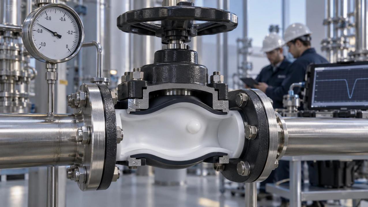
The bulge may first be noticed after evacuation, although the same valve looked ordinary while it carried liquid. That contrast matters. The medium may be unchanged, yet the direction of loading is different once the vacuum pump is running. Instead, evacuation turned the usual loading around.
The process fluid is on the side that can be evacuated directly. Gas in a pocket behind the liner has a different route out, and that route may take longer. Until it has emptied, the pocket can press a portion of lining inward. There is also absorbed process material to consider: as bore pressure falls, some may come out as vapor. The backing and the shape of the unsupported patch determine how that pressure becomes movement. A chemical-resistance statement on the resin tells the buyer little about this brief mechanical load.
Pressure reversal is one candidate, not a diagnosis from appearance alone. Incomplete backing, damage left by an earlier impact, local forming variation, or an assembly fault can produce a related shape. The useful question is narrower: does the damaged location and its timing match the pressure reversal that actually occurred?
Where Can the Reverse Pressure Develop?
Start with the position rather than the resin label. Around the weir and the transition into each flange, the metal support changes shape; a raised patch must be read against the geometry beneath that particular spot. Corners, formed transitions, and recesses may place a different liner thickness over a different backing condition than the straight section of bore. A broad slack-looking wave suggests distributed movement; a short firm blister suggests a more confined feature.
One Gauge Cannot Read Both Sides of the Liner
Look at the first moments of pump-down, before the warm valve has cooled. The gauge on the line follows the bore. A closed pocket behind the lining has no gauge of its own. When its only pressure path is slow, the bore may already be at low absolute pressure while that pocket remains nearer the pressure it had moments earlier. The lining briefly carries the difference.
Absorbed material creates another route. Heating and exposure can allow vapor to enter the polymer. A falling external pressure then favors release. Its contribution still has to be investigated alongside the other possible causes of the raised shape.
The support beside a weir or flange can differ even when both constructions use PTFE. PFA, too, is a polymer description; the formed contour and wall thickness remain details of the assembly. A recent hot wash adds another difference: the liner may begin evacuation before it has cooled, while absorbed material may be releasing vapor. Reading only the resin description leaves that part of the event unexplained.
Which Part Has Changed Shape: the Liner or the Diaphragm?
The phrase “deformed diaphragm” is often used for anything visible through the port. The stationary liner follows the inside of the body; the diaphragm moves and is clamped at the body-bonnet joint. Their failure clues are different.
What Do the Blister Edge and Compressor Marks Show?
The first views should be of the undisturbed bulge. Views from each port can locate it against the weir, flange transition, and known flow direction. Touch adds another clue: a compressible pocket, a firm bump, and a loose shallow wave do not lead to the same examination. An early cut vents the feature and removes its original edge, leaving less for a materials laboratory to interpret.
Read the removed diaphragm on its own terms. A permanent fold through its flexing zone can point toward travel or repeated bending. A stretched middle, an eccentric compressor imprint, or wear along one compressor edge connects the damage more directly to travel and alignment. Excess travel continues loading the flexible center after the valve has already reached shutoff, without requiring the body liner to lift. Common heat and chemistry do not make those marks equivalent. Wear beside the compressor follows movement; a blister in the liner raises the separate question of backing and pressure across that patch.
Which Pressure Change Was Happening When the Liner Moved?
Steady production values may completely miss the event. The important interval could begin when a vessel drains, when steam condenses in a blocked section, or when vacuum is broken after a hold. A trend covering those minutes is far more useful than a monthly minimum taken from another instrument.
Absolute Pressure Changes the Meaning of “Full Vacuum”
A gauge value below zero is relative to local atmosphere. Absolute pressure describes the gas pressure that remained in the line. Even then, one minimum number is not the whole load. A fast fall to that value creates a different pressure imbalance from a slow drawdown. Holding there for twenty minutes is different from venting at once.
Valve position can split the history in two. With the valve closed, its vessel port may be evacuated while the far port remains much nearer atmospheric pressure. A warm cavity trapped between closed equipment may follow a third path. This is why two valves of the same purchase description can come out of the same operation with different marks.
Place temperature on the pump-down trace itself. The liner might start at batch temperature, retain rinse liquid, and cool as pressure in the bore is dropping. Media concentration and impurities describe what was available to enter or affect the polymer. Cooling rate describes how both vapor pressure and material stiffness were changing. A proposed permeation explanation becomes stronger only when these details agree with the examination.
Did the Reference Valve Experience the Same Transient?
Use a valve that remained flat only after checking what it shares with the damaged unit. A change in size, liner build, actuator, manufacturing lot, pipe position, or starting temperature can alter the comparison before the materials are considered.
Which Conditions Must Match Between the Two Runs?
For a trial about drawdown speed, the same valve construction needs to begin at the same temperature on both runs. Otherwise a changed response could come from the hardware or the warmth rather than the pressure fall. Testing a different size may help explain a suspected pocket behind the lining, yet that experiment leaves the installed size unqualified. The proposed correction still has to be demonstrated on the construction the buyer will use.
Reaching the incident minimum briefly is not a reproduction of the incident. The trial must follow the observed fall in pressure, remain low for the same interval, and use the same type of venting at the end. A safer substitute may be needed, with the limitation that it may soak into and leave the polymer at another rate. The substitution therefore narrows the conclusion.
What Must Change Before the Valve Returns to Service?
Installing the same valve again also restores the same pump-down and support conditions. The restart decision needs one physical reason why the damaging differential will not recur. The evidence may support a differently backed liner, correction of compressor travel, a slower fall in pressure, or a controlled vent back to atmosphere.
How Does the Correction Interrupt the Load?
After restart, an inspection of the liner can reveal whether the early cycles are bringing the bulge back. That observation belongs beside the tested pressure-temperature path. A hotter start or a faster pump-down would still be a new operating condition for this size and liner.
An enquiry that says only ‘vacuum duty’ leaves the transient for the supplier to guess. The useful description starts at valve temperature, continues through the minimum absolute pressure and the time spent there, and ends with venting and valve position. The medium and size, liner construction, diaphragm, orientation, and actuator identify the assembly that experienced that sequence. This makes the reply about one assembly’s pressure journey rather than a general resin preference.
Discuss the Actual Valve and Transient
Miwival’s diaphragm valve page covers weir and straight-through forms applied to corrosive or abrasive media as well as pressure and vacuum duties. The chemical-industry application page gives additional process context. The company profile and contact channel provide a route for sending the proposed construction and operating transient for review. Public product information starts that discussion; the written response for the selected assembly defines its project use.
Conclusion
A bulge that appears during evacuation can result when bore pressure drops ahead of pressure or vapor behind the liner. Its position tells which support detail is involved; the event trace shows whether the required imbalance was possible. Comparing another valve helps only after construction and exposure differences are accounted for. Restart becomes reasonable when a construction or process change interrupts the specific load path found in the investigation.
FAQs
Can a chemically compatible lining still fail during evacuation?
Yes. Chemical resistance and resistance to an outward pressure differential are different properties of the installed construction.
Why inspect the blister before making a cut?
A cut releases anything inside and changes both the edge and stiffness of the raised patch. After that change, a confined pressure feature is harder to separate from ordinary surface damage.
Why use absolute pressure in the review?
It reports the gas pressure left in the pipe without shifting with local atmospheric conditions. The rate of pressure fall and the dwell remain necessary because liner load develops over time, not from the minimum reading alone.
Does one undamaged valve clear the design?
No. It is a sound reference only when its build, pipe location, temperature history, and complete vacuum cycle are close to those of the damaged unit.


 consult
 WHATSAPP
 leave message
 top